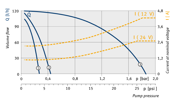
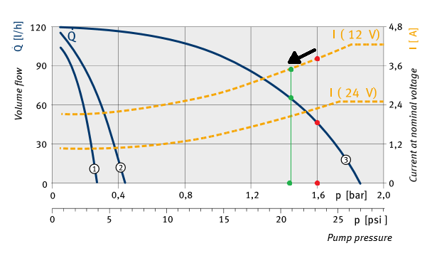
Your basic premise is flawed. Moving left and right on the graph correlates to different flow rates if everything is kept the same while the pressure is changed. The change in power comes from the change in RPM and is unintentional.
In a vehicle there is generally only one system voltage available. Further fuel pumps are generally run directly from straight system voltage (there are some exceptions, Ford for example sometimes modulates their pumps). DC motors have a curious effect, their rotor winding resistance is dependent on their RPM. When the motor is stalled (zero RPM) only the actual real resistance of the rotor windings dominates. The rotor winding resistance is very very low. As the motor speeds up the resistance also goes up. At full unloaded RPM there is a balance point where because of the high resistance the motor can't spin any faster and the motor consumes the least amount of current. Because the voltage is kept constant the slower the motor spins the more power it consumes due to the increase in current.
Change in RPM in a motor come from the load on that motor. In a pump load comes form generating high pressure which in turn slows the motor down. Moving high volume still causes a load but substantially less. Because of the lower load the pump spins at a higher RPM.
Worn brushes would increase the base resistance of the rotor windings. This would have two effects. First, because of the higher resistance at the lower RPM the pump will consume less current which results in less power. This reduction of power will reduce the maximum pressure the pump can achieve. Second, the increased resistance will cause the pump to reach the balance point at a lower RPM, limiting the maximum volume.
The ultimate result is that the yellow line indicating the current will get slid down and as a result the blue line will also get slid down.


