0

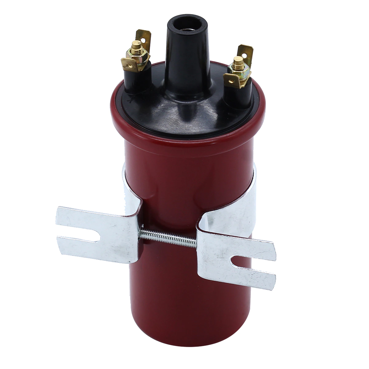
How can I test and find the polarity of an ignition coil (that's not connected to a car) using a multi-meter.

Just to let you know coils can have polarity when DC Voltage is placed on them. https://mossmotoring.com/coil-polarity/

img1

I have different high voltage coils I need to test for polarity not only an ignition coil. But I think I can use the same test to find the polarity of the ignition coil to check the polarity of the other coils.

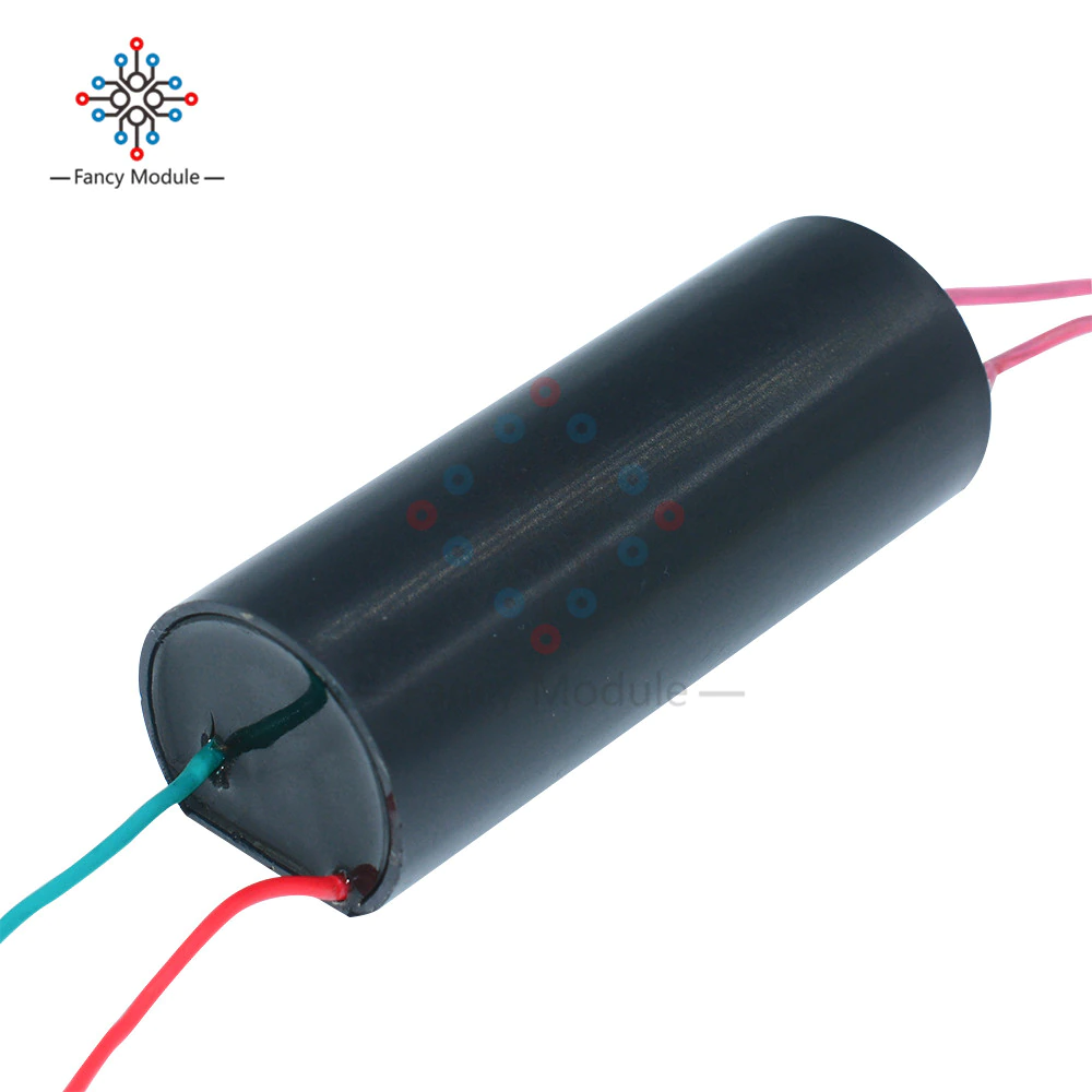
Example of another coil I need to test for polarity. Boost Step Up Power Module High Voltage Generator Converter (I do know the polarity of the red and green input wires, it's the two red output wires I'm trying to find / test the polarities of.)

I found a video that says it outputs High Voltage DC but want to verify the polarity (If the video is correct about being high voltage DC) https://youtu.be/L9Aq3BlNq9k?t=881 ...

Data that's on the website.

DC 3V-6V Bis 400kV 400000V Boost Step Up Power Module High Voltage Generator Converter

Description:
Input voltage: DC 3 V to 6 V
Input current: 2 A - 5 A
High pressure type: the type of pulse current
Output voltage: 400000 v(Please pay attention to safety)
High pressure discharge distance between: 10 mm - 20 mm
The output high voltage wire length: 100 mm
Input power cord length: 100 mm (the red line is positive)
Wiring:
Red and green power connection red line:"+" green line "-"
output : the other side ,same color cable
Please notice:
The high-voltage module should avoid the use of electricity in high voltage no-load . (Power must be adjusted to a suitable distance to the high-voltage output line , battery capacity is proportional to the distance and the use of the high-pressure arc ( not a voltage as high as possible , you must provide enough current ) . Experimental test of the arc distance from short to long , Do not exceed the maximum arc distance electricity, energy can not be released due to high pressure , can easily damage the module. )
Work: intermittent , continuous work does not allow more than 1 minute and the output side does not allow shorting . Improper voltage and long working hours easily damaged module
Package included:
1 x DC 3v-6v to 400kV 400000V Boost Step-up Power Module High-voltage Generator

img2

2 Answers 2

2

The only reason that the car HT coil in your first picture has a polarity is because one of the secondary coil connections is common with one of the primary coil connections. That is why there is only 3 terminals. The coil is designed to have pulsed DC on the primary.

The other HT coil you have has 4 terminals, so there is no common terminal. The coils are totally isolated. If its application is a voltage booster, it will be designed to run on AC.

Are you sure there are no electronics in the coil in the second photo? Is it meant to be powered by DC and has some electronics in it that generates AC for the transformer?

9
  • It's powered by DC and I was trying to find the polarity without blowing my meter. I wanted to try it with different ignition coils and several other type of coils to see the different effects they create. I wanted to find the correct polarity of each output wire to put in my notes since this may cause different effects (Ebner effect) youtube.com/watch?v=w1ha6LCzRgU much like the link above the polarity may cause slight changes in things. mossmotoring.com/coil-polarity
    – Rick T
    Commented May 12, 2022 at 21:22
  • The electronics in the device will be creating an AC current for the transformer, therefore the output will likely be a high voltage AC current on the output, hence no polarity.
    – HandyHowie
    Commented May 12, 2022 at 21:30
  • Do you have the datasheet for that device?
    – HandyHowie
    Commented May 12, 2022 at 21:57
  • 1
    I wonder if you could use electrolysis to indicate polarity - chemistry.stackexchange.com/questions/62591/…
    – HandyHowie
    Commented May 13, 2022 at 5:53
  • 1
    Just found this same question - reddit.com/r/AskElectronics/comments/lfim0i/…
    – HandyHowie
    Commented May 13, 2022 at 5:58
0

Thanks to HandyHowie for getting me this far.

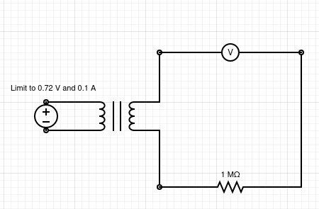
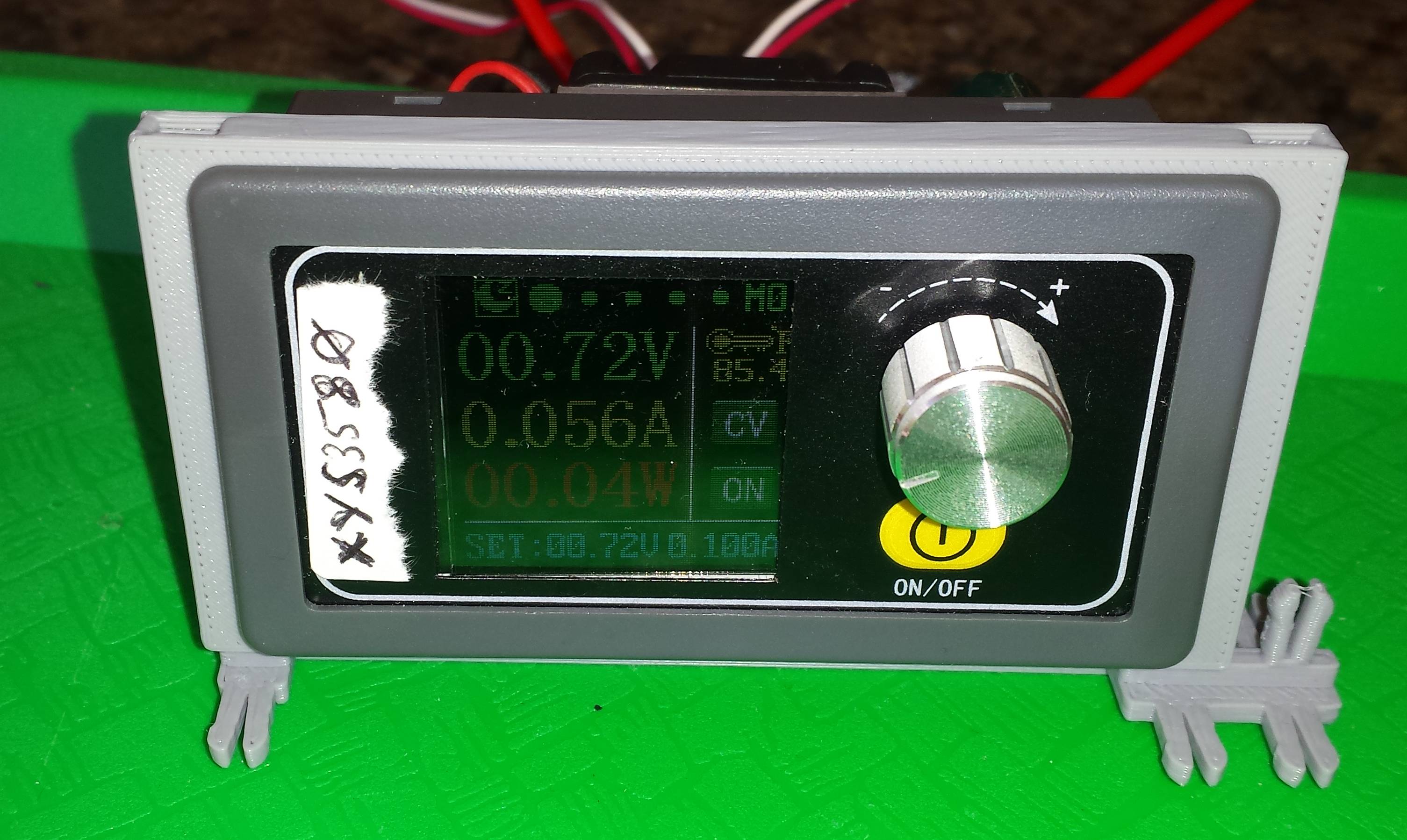
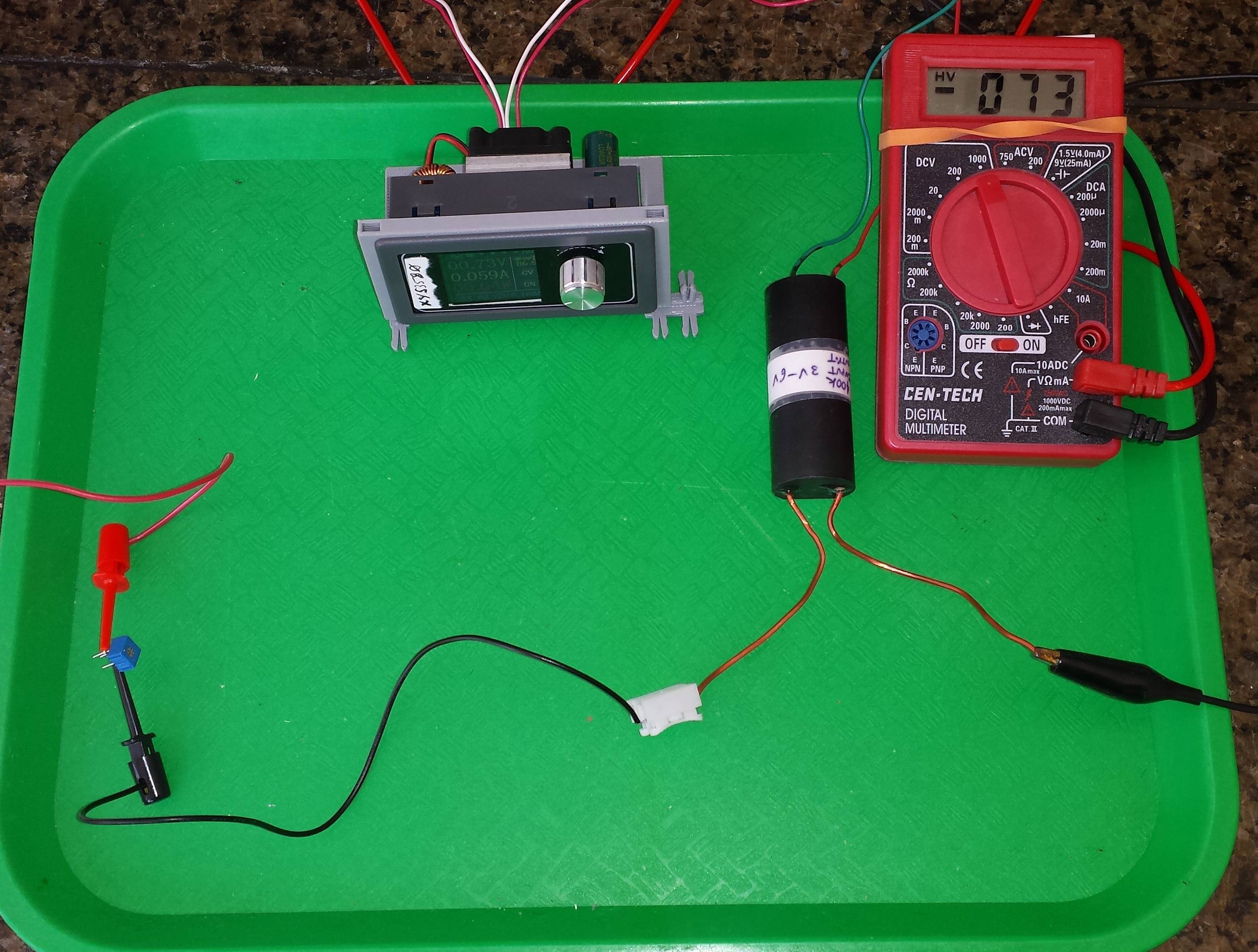
Since this was also asked somewhere else I thought I would give a full answer that worked for me. I used an XYS3580 buck boost convertor to limit the voltage going to the transformer to 0.72V and 0.1A (any DC power supply that can produce these low levels will work) and a 1Meg ohm resistor is series.

As you can see the meter is showing a negative value so the polarity / meter leads are reversed.

Circuit:

imgg1

img2

img3

Also this video may help with higher voltages. link

You must log in to answer this question.

Not the answer you're looking for? Browse other questions tagged .