2

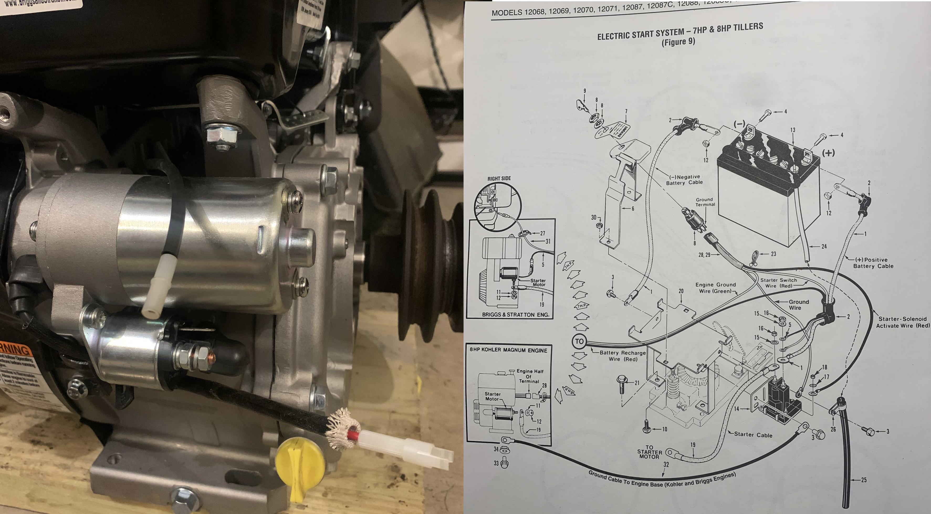
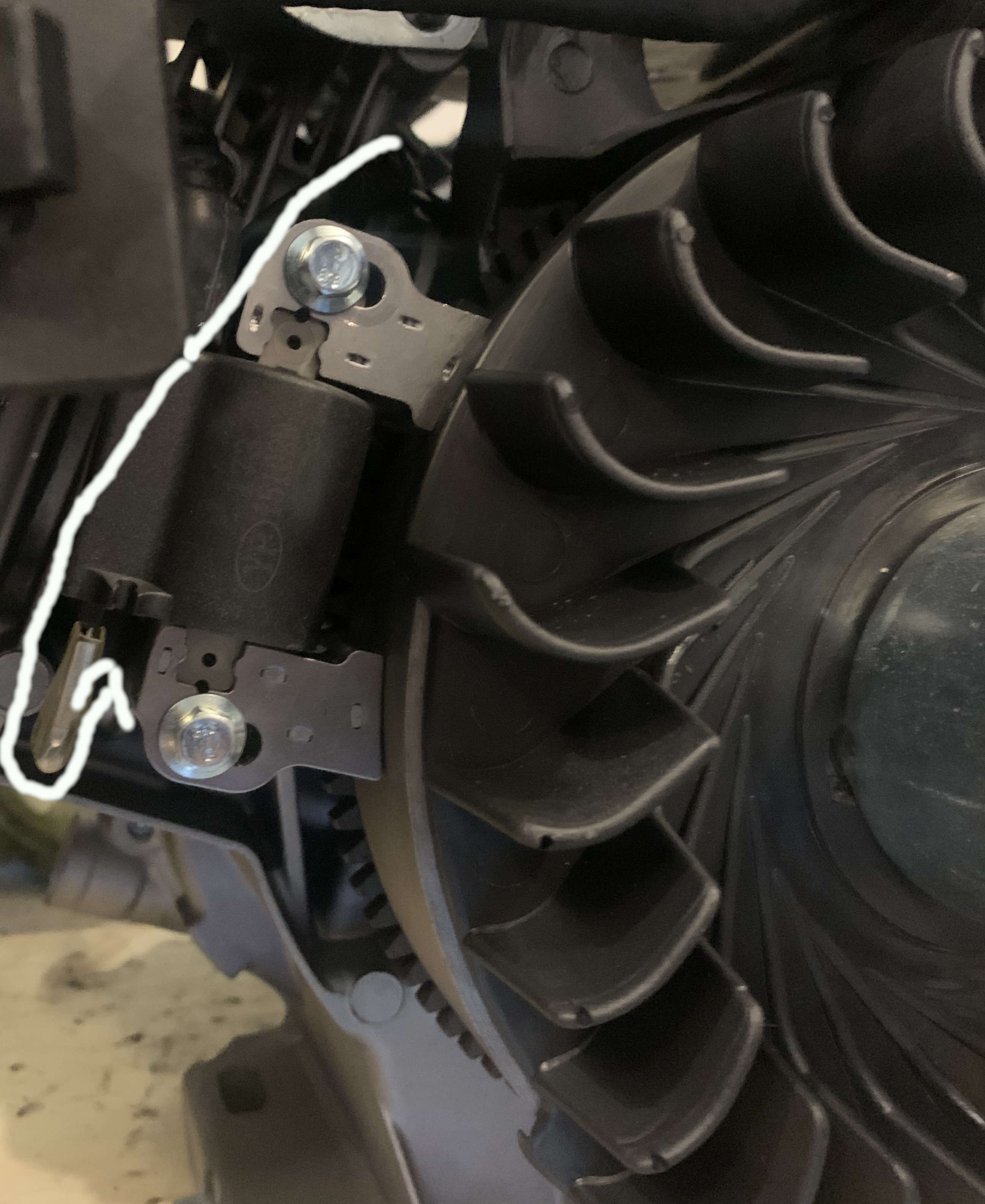
I have an old Troy Bilt Horse tiller, model 12090 with a 8hp Briggs Industrial Plus 196437, type 013401, code 9612181A. I bought a direct replacement engine, Briggs 19N137-0084 (https://www.smallenginewarehouse.com/19N137-0084). I have a question about wiring: the engine is electric start, but came without the starter switch. It has 2 wires hanging out, red and black (see picture), one male, one female. Manual doesn't explain what they are and I can't see where they end. I think red is battery charging wire, black is engine ground. I have a wiring diagram from the parts manual for my tiller (second pic).

I was planning just wiring it up exactly like the diagram shows, except now the solenoid is on the engine itself, so the red wire I'd just loop back to the solenoid terminal, the black wire I was planning on connecting to the starter switch ground. Is this correct? Thank you enter image description hereThe two wires on the left, Troy Bilt Horse wring diagram on right enter image description here
1
  • Welcome to Motor Vehicle Maintenance & Repair! Commented May 22, 2022 at 2:51

1 Answer 1

1

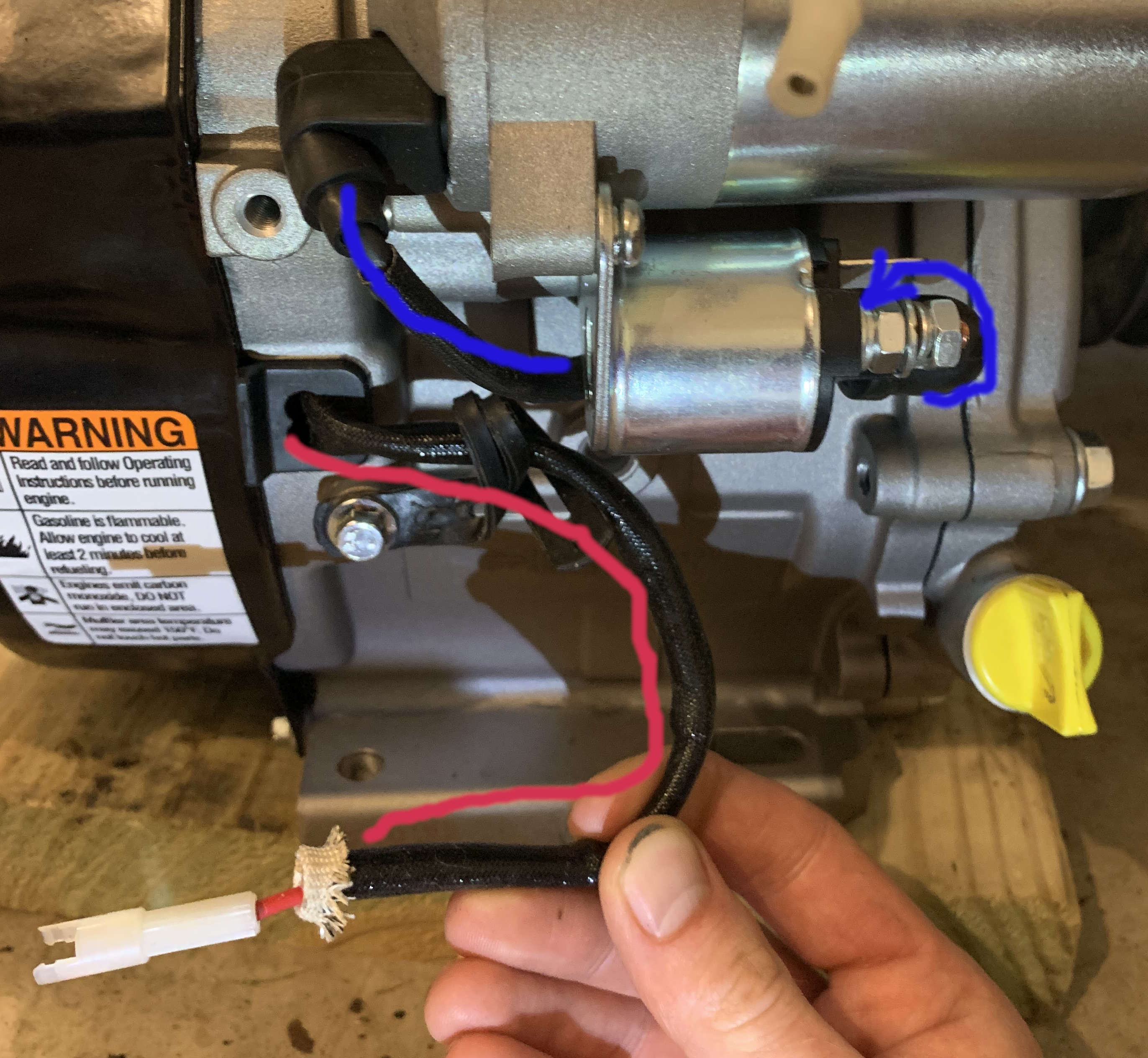
After seeing your latest photos, I would say that the black wire is used to stop the engine running, since it looks like it is connected to the Ignition coil. To stop the engine, the black wire needs to be shorted to ground. While the engine is running, the black wire should be open circuit.

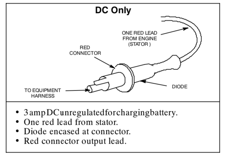
The red wire is likely the battery charging supply as shown in the wiring diagram from the page you supplied. I would suggest you test the output from this with a voltmeter before you connect it to anything. If the wiring diagram is correct, there may be a diode in the connector. If this is correct, it will want to connect to the battery positive terminal, which will also be available on the starter solenoid.

enter image description here

2
  • I agree- I am pretty certain the black wire is a kill wire, and as such I was going to wire it to the starter key switch (like what the diagram refers to as engine ground wire). For the red wire, I am also pretty sure it is a battery charge wire. So basically following the diagram from the tiller manual. Good call on testing before connecting- what would you test for? That it shows 12V?
    – biostatrat
    Commented May 22, 2022 at 22:36
  • Yes, I would test that it is putting out 12-14 V DC when the engine is running.
    – HandyHowie
    Commented May 23, 2022 at 5:29

You must log in to answer this question.

Not the answer you're looking for? Browse other questions tagged .