2

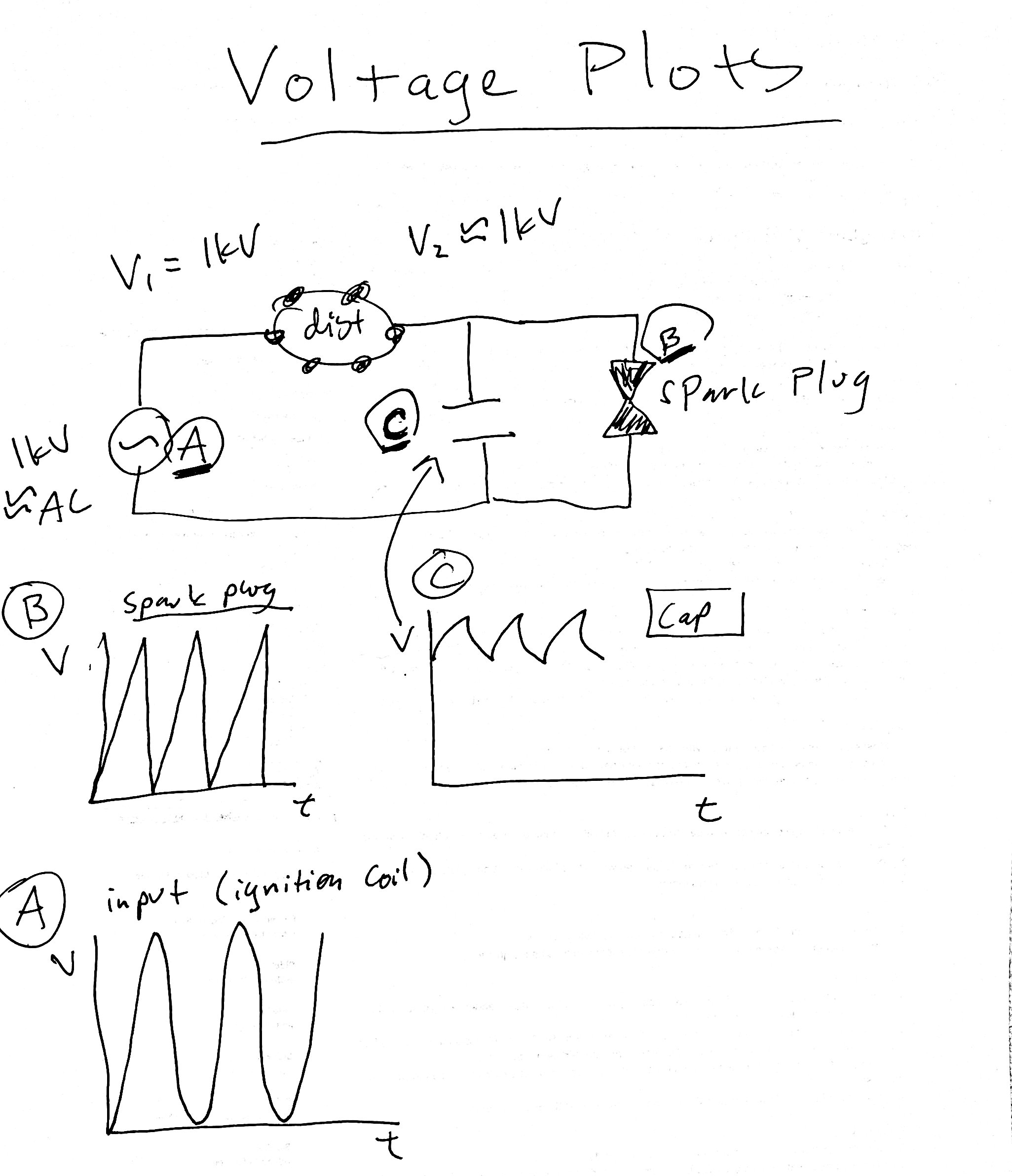
Here is a post I found, but it doesnt clearly explain why arcing is suppressed with a cap(acitor)

How the Ignition System Works

by Malcolm Holser

The way the ignition works is this: You connect a coil to some electricity, and it builds up a magnetic field. You stop feeding the electricity, and the field collapses, inducing flow. The voltage, in this open circuit, builds rapidly toward infinity and eventually it must go somewhere, and arcs across whatever is handy.

Relays do this, and generate a back-spike when they are disengaged, arcing across the contacts of the controlling switch. Often, a "diode clamp" will be placed across the relay coil to prevent this. (always in electronics that cannot tolerate voltage spikes).

The ignition coil is really two coils intertwined, with the leads to one going to the spark plug, and the leads to the other going to the points. Your points close, and a magnetic field builds up. They must stay closed long enough (they DWELL closed for a bit!) to energize the field. They open, and the field collapses. The inductance of the collaspsing field does not care which of the two intermingled coils created it -- it dumps into both, but because of the way they are wound, it mostly dumps into the spark-plug side. Enough gets into the points-side, though, that there will be a spark across them as well. The condensor is there to absorb this. Without a condensor, your ignition will work fine, but your points will very rapidly pit because of the arcing, and may weld themselves together. Alway replace the condensor with the points -- it is more common that a poor condensor has caused the points to fail than the points wearing on their own.

http://www.hydra-glide.com/phpBB3/viewtopic.php?t=7208!
enter image description here

3
  • 1
    It's not clear how much detail you want (and a full answer might be "study an AC circuits course in an electrical engineering degree") but in simple terms, when you suddenly switch off a coil the energy stored in its magnetic field has to go somewhere, it tries to produce a pulse of current to get rid of it. But the current can't flow in the wires of circuit because you just broke the circuit! So it jumps a gap and creates a spark, The purpose of the capacitor is the absorb the current without the spark in the low-tension circuit, and protecting the points from being burned.
    – alephzero
    Commented Jan 8, 2020 at 9:38
  • 1
    @alephzero I believe that your comment isn't quite correct (but correct me if I am wrong). I believe that the capacitor continues to allow current into the coil after the points have opened, so delaying the collapse of the magnetic field sufficiently to protect the points.(see my answer)
    – HandyHowie
    Commented Jan 9, 2020 at 7:46
  • I think I'll post this question in physics. Where does the ignition coil get its input voltage cycle from? And is it ac or dc? I assume the cap stabilizes the voltage, but arcing is caused by high voltage difference. Actually I get I now I think.----- the capacitor reduces the voltage difference across the distributor, but doesn't do anything about the voltage change across the spark plug gap. The capacitor stores charge, and keeps the voltage after the distributor High.
    – Dan Z
    Commented Jan 12, 2020 at 4:44

2 Answers 2

4

Since the condenser (capacitor) is connected in parallel to the point's contacts, when the points open the condenser then allows a small amount of current to briefly continue flowing through the capacitor until it is fully charged, therefore allowing the contacts to open fully without arcing.

Once current into the primary coil stops flowing the magnetic field in the coil collapses and produces the high voltage. Since the points are now open, there is little or no arcing at the points.

1
  • Marking this as the answer because of why not. I think my plots are right
    – Dan Z
    Commented Jan 18, 2020 at 23:01
0

The capacitor starts charging as soon as the contacts start to open - that is how it prevents the burning, or pitting, of the contacts. It then discharges through the points ready for next time.

The basic equation for the amount of charge in a capacitor is:

 Q = I * t

where Q is the amount of charge, I is current and t is time.

The details of how a capacitor functions is off-topic for this stack, but here is a link to one (of many) webpages giving more detail : https://www.build-electronic-circuits.com/how-does-a-capacitor-work/

Edit, based on your final comment, the input voltage to the coil on a car is 12v (or between 12 and 15v when the engine is running) and it is DC as that is the system as designed.

You must log in to answer this question.

Not the answer you're looking for? Browse other questions tagged .