Commonmark migration
Source Link

The door lock/unlock relays are built into the multiplex unit on that year CR-V and are not serviceable (See Figs. 1 & 2). To replace it you'd either have to replace the whole multiplex unit or crack it open, trace out the board and solder in a new relay.

To test the relay you would have to gain access to the back of the multiplex unit connector M (22 in Fig 2). On a lock command the driver door lock relay powers terminal 9 and there should be a ground on terminal 7. And the other way around on an unlock command.

Since you already replaced the driver door lock actuator I'd suggest you take a look at the wiring. A common failure point is in the rubber sleeve that goes from the interior to the door.

Fig 1. Fig 1

Fig 2.

Socket Ref Terminal Connects to


A 2 5 Dashboard wire harness B (see DASHBOARD WIRE HARNESS B )
B 3 6 Dashboard wire harness B (see DASHBOARD WIRE HARNESS B )
C 1 14 Dashboard wire harness B (see DASHBOARD WIRE HARNESS B )
D 4 12 ECM/PCM wire harness (see ECM/PCM WIRE HARNESS )
E 5 13 ECM/PCM wire harness (see ECM/PCM WIRE HARNESS )
F 19 12 Engine compartment wire harness (see ENGINE COMPARTMENT WIRE HARNESS (DASH BRANCH) )
G 9 10 Engine compartment wire harness (see ENGINE COMPARTMENT WIRE HARNESS (DASH BRANCH) )
H 8 3 Engine compartment wire harness (see ENGINE COMPARTMENT WIRE HARNESS (DASH BRANCH) )
I 20 5 Engine compartment wire harness (see ENGINE COMPARTMENT WIRE HARNESS (DASH BRANCH) )
J 21 8 Engine compartment wire harness (see ENGINE COMPARTMENT WIRE HARNESS (DASH BRANCH) )
K 23 17 Dashboard wire harness A (see DASHBOARD WIRE HARNESS A (LEFT BRANCH) )
L 24 10 Dashboard wire harness A (see DASHBOARD WIRE HARNESS A (LEFT BRANCH) )
M 22 12 Dashboard wire harness A (see DASHBOARD WIRE HARNESS A (LEFT BRANCH) )
N 27 6 Dashboard wire harness A (see DASHBOARD WIRE HARNESS A (LEFT BRANCH) )
O 26 12 Dashboard wire harness A (see DASHBOARD WIRE HARNESS A (LEFT BRANCH) )
P 7 18 ECM/PCM wire harness (see ECM/PCM WIRE HARNESS )
Q 6 8 ECM/PCM wire harness (see ECM/PCM WIRE HARNESS )
R 10 6 ECM/PCM wire harness (see ECM/PCM WIRE HARNESS )
Power window relay 12 4
S 25 2 ECM/PCM wire harness (see ECM/PCM WIRE HARNESS )
Starter cut relay 14 4
T 18 3 Multiplex control inspection connector
Taillight relay 13 4
Turn signal/hazard relay 11 3
U 15 1 Optional connector
V 16 4 Optional connector
W (Memory erase signal (MES) connector) 17 2 ECM/PCM wire harness (see ECM/PCM WIRE HARNESS )
X 28 8 (Plugs directly into the multiplex control unit) Y 29 13 (Plugs directly into the multiplex control unit)

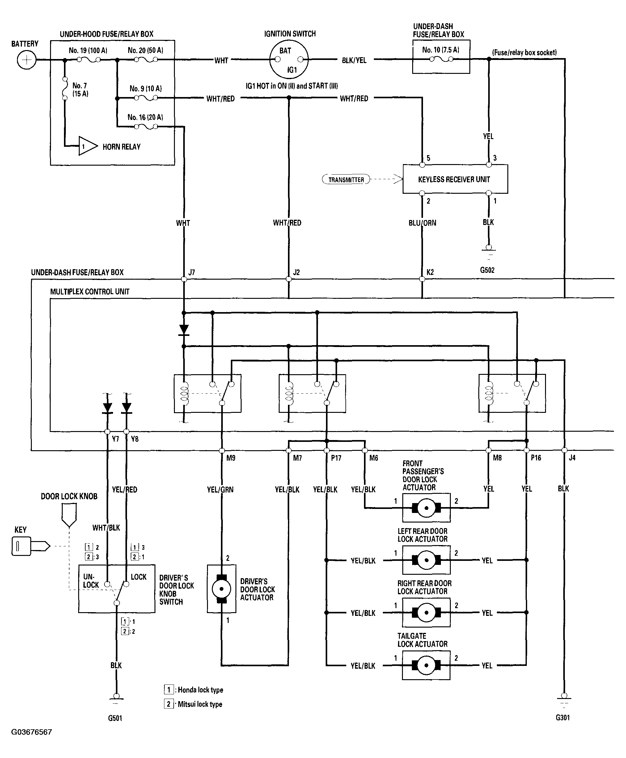
Fig 2

The door lock/unlock relays are built into the multiplex unit on that year CR-V and are not serviceable (See Figs. 1 & 2). To replace it you'd either have to replace the whole multiplex unit or crack it open, trace out the board and solder in a new relay.

To test the relay you would have to gain access to the back of the multiplex unit connector M (22 in Fig 2). On a lock command the driver door lock relay powers terminal 9 and there should be a ground on terminal 7. And the other way around on an unlock command.

Since you already replaced the driver door lock actuator I'd suggest you take a look at the wiring. A common failure point is in the rubber sleeve that goes from the interior to the door.

Fig 1. Fig 1

Fig 2.

Socket Ref Terminal Connects to


A 2 5 Dashboard wire harness B (see DASHBOARD WIRE HARNESS B )
B 3 6 Dashboard wire harness B (see DASHBOARD WIRE HARNESS B )
C 1 14 Dashboard wire harness B (see DASHBOARD WIRE HARNESS B )
D 4 12 ECM/PCM wire harness (see ECM/PCM WIRE HARNESS )
E 5 13 ECM/PCM wire harness (see ECM/PCM WIRE HARNESS )
F 19 12 Engine compartment wire harness (see ENGINE COMPARTMENT WIRE HARNESS (DASH BRANCH) )
G 9 10 Engine compartment wire harness (see ENGINE COMPARTMENT WIRE HARNESS (DASH BRANCH) )
H 8 3 Engine compartment wire harness (see ENGINE COMPARTMENT WIRE HARNESS (DASH BRANCH) )
I 20 5 Engine compartment wire harness (see ENGINE COMPARTMENT WIRE HARNESS (DASH BRANCH) )
J 21 8 Engine compartment wire harness (see ENGINE COMPARTMENT WIRE HARNESS (DASH BRANCH) )
K 23 17 Dashboard wire harness A (see DASHBOARD WIRE HARNESS A (LEFT BRANCH) )
L 24 10 Dashboard wire harness A (see DASHBOARD WIRE HARNESS A (LEFT BRANCH) )
M 22 12 Dashboard wire harness A (see DASHBOARD WIRE HARNESS A (LEFT BRANCH) )
N 27 6 Dashboard wire harness A (see DASHBOARD WIRE HARNESS A (LEFT BRANCH) )
O 26 12 Dashboard wire harness A (see DASHBOARD WIRE HARNESS A (LEFT BRANCH) )
P 7 18 ECM/PCM wire harness (see ECM/PCM WIRE HARNESS )
Q 6 8 ECM/PCM wire harness (see ECM/PCM WIRE HARNESS )
R 10 6 ECM/PCM wire harness (see ECM/PCM WIRE HARNESS )
Power window relay 12 4
S 25 2 ECM/PCM wire harness (see ECM/PCM WIRE HARNESS )
Starter cut relay 14 4
T 18 3 Multiplex control inspection connector
Taillight relay 13 4
Turn signal/hazard relay 11 3
U 15 1 Optional connector
V 16 4 Optional connector
W (Memory erase signal (MES) connector) 17 2 ECM/PCM wire harness (see ECM/PCM WIRE HARNESS )
X 28 8 (Plugs directly into the multiplex control unit) Y 29 13 (Plugs directly into the multiplex control unit)
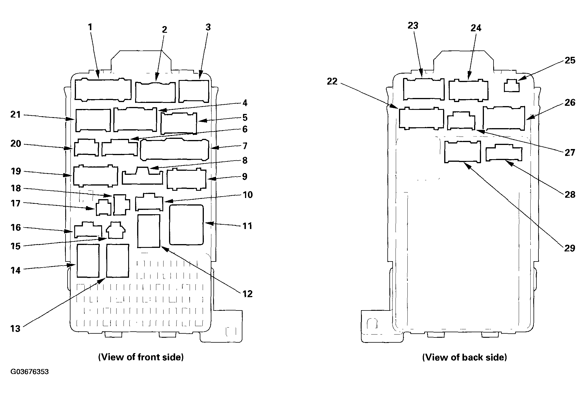
Fig 2

The door lock/unlock relays are built into the multiplex unit on that year CR-V and are not serviceable (See Figs. 1 & 2). To replace it you'd either have to replace the whole multiplex unit or crack it open, trace out the board and solder in a new relay.

To test the relay you would have to gain access to the back of the multiplex unit connector M (22 in Fig 2). On a lock command the driver door lock relay powers terminal 9 and there should be a ground on terminal 7. And the other way around on an unlock command.

Since you already replaced the driver door lock actuator I'd suggest you take a look at the wiring. A common failure point is in the rubber sleeve that goes from the interior to the door.

Fig 1. Fig 1

Fig 2.

Socket Ref Terminal Connects to

A 2 5 Dashboard wire harness B (see DASHBOARD WIRE HARNESS B )
B 3 6 Dashboard wire harness B (see DASHBOARD WIRE HARNESS B )
C 1 14 Dashboard wire harness B (see DASHBOARD WIRE HARNESS B )
D 4 12 ECM/PCM wire harness (see ECM/PCM WIRE HARNESS )
E 5 13 ECM/PCM wire harness (see ECM/PCM WIRE HARNESS )
F 19 12 Engine compartment wire harness (see ENGINE COMPARTMENT WIRE HARNESS (DASH BRANCH) )
G 9 10 Engine compartment wire harness (see ENGINE COMPARTMENT WIRE HARNESS (DASH BRANCH) )
H 8 3 Engine compartment wire harness (see ENGINE COMPARTMENT WIRE HARNESS (DASH BRANCH) )
I 20 5 Engine compartment wire harness (see ENGINE COMPARTMENT WIRE HARNESS (DASH BRANCH) )
J 21 8 Engine compartment wire harness (see ENGINE COMPARTMENT WIRE HARNESS (DASH BRANCH) )
K 23 17 Dashboard wire harness A (see DASHBOARD WIRE HARNESS A (LEFT BRANCH) )
L 24 10 Dashboard wire harness A (see DASHBOARD WIRE HARNESS A (LEFT BRANCH) )
M 22 12 Dashboard wire harness A (see DASHBOARD WIRE HARNESS A (LEFT BRANCH) )
N 27 6 Dashboard wire harness A (see DASHBOARD WIRE HARNESS A (LEFT BRANCH) )
O 26 12 Dashboard wire harness A (see DASHBOARD WIRE HARNESS A (LEFT BRANCH) )
P 7 18 ECM/PCM wire harness (see ECM/PCM WIRE HARNESS )
Q 6 8 ECM/PCM wire harness (see ECM/PCM WIRE HARNESS )
R 10 6 ECM/PCM wire harness (see ECM/PCM WIRE HARNESS )
Power window relay 12 4
S 25 2 ECM/PCM wire harness (see ECM/PCM WIRE HARNESS )
Starter cut relay 14 4
T 18 3 Multiplex control inspection connector
Taillight relay 13 4
Turn signal/hazard relay 11 3
U 15 1 Optional connector
V 16 4 Optional connector
W (Memory erase signal (MES) connector) 17 2 ECM/PCM wire harness (see ECM/PCM WIRE HARNESS )
X 28 8 (Plugs directly into the multiplex control unit) Y 29 13 (Plugs directly into the multiplex control unit)

Fig 2

Source Link
Ben
  • 10.7k
  • 4
  • 22
  • 53

The door lock/unlock relays are built into the multiplex unit on that year CR-V and are not serviceable (See Figs. 1 & 2). To replace it you'd either have to replace the whole multiplex unit or crack it open, trace out the board and solder in a new relay.

To test the relay you would have to gain access to the back of the multiplex unit connector M (22 in Fig 2). On a lock command the driver door lock relay powers terminal 9 and there should be a ground on terminal 7. And the other way around on an unlock command.

Since you already replaced the driver door lock actuator I'd suggest you take a look at the wiring. A common failure point is in the rubber sleeve that goes from the interior to the door.

Fig 1. Fig 1

Fig 2.

Socket Ref Terminal Connects to

A 2 5 Dashboard wire harness B (see DASHBOARD WIRE HARNESS B )
B 3 6 Dashboard wire harness B (see DASHBOARD WIRE HARNESS B )
C 1 14 Dashboard wire harness B (see DASHBOARD WIRE HARNESS B )
D 4 12 ECM/PCM wire harness (see ECM/PCM WIRE HARNESS )
E 5 13 ECM/PCM wire harness (see ECM/PCM WIRE HARNESS )
F 19 12 Engine compartment wire harness (see ENGINE COMPARTMENT WIRE HARNESS (DASH BRANCH) )
G 9 10 Engine compartment wire harness (see ENGINE COMPARTMENT WIRE HARNESS (DASH BRANCH) )
H 8 3 Engine compartment wire harness (see ENGINE COMPARTMENT WIRE HARNESS (DASH BRANCH) )
I 20 5 Engine compartment wire harness (see ENGINE COMPARTMENT WIRE HARNESS (DASH BRANCH) )
J 21 8 Engine compartment wire harness (see ENGINE COMPARTMENT WIRE HARNESS (DASH BRANCH) )
K 23 17 Dashboard wire harness A (see DASHBOARD WIRE HARNESS A (LEFT BRANCH) )
L 24 10 Dashboard wire harness A (see DASHBOARD WIRE HARNESS A (LEFT BRANCH) )
M 22 12 Dashboard wire harness A (see DASHBOARD WIRE HARNESS A (LEFT BRANCH) )
N 27 6 Dashboard wire harness A (see DASHBOARD WIRE HARNESS A (LEFT BRANCH) )
O 26 12 Dashboard wire harness A (see DASHBOARD WIRE HARNESS A (LEFT BRANCH) )
P 7 18 ECM/PCM wire harness (see ECM/PCM WIRE HARNESS )
Q 6 8 ECM/PCM wire harness (see ECM/PCM WIRE HARNESS )
R 10 6 ECM/PCM wire harness (see ECM/PCM WIRE HARNESS )
Power window relay 12 4
S 25 2 ECM/PCM wire harness (see ECM/PCM WIRE HARNESS )
Starter cut relay 14 4
T 18 3 Multiplex control inspection connector
Taillight relay 13 4
Turn signal/hazard relay 11 3
U 15 1 Optional connector
V 16 4 Optional connector
W (Memory erase signal (MES) connector) 17 2 ECM/PCM wire harness (see ECM/PCM WIRE HARNESS )
X 28 8 (Plugs directly into the multiplex control unit) Y 29 13 (Plugs directly into the multiplex control unit)

Fig 2