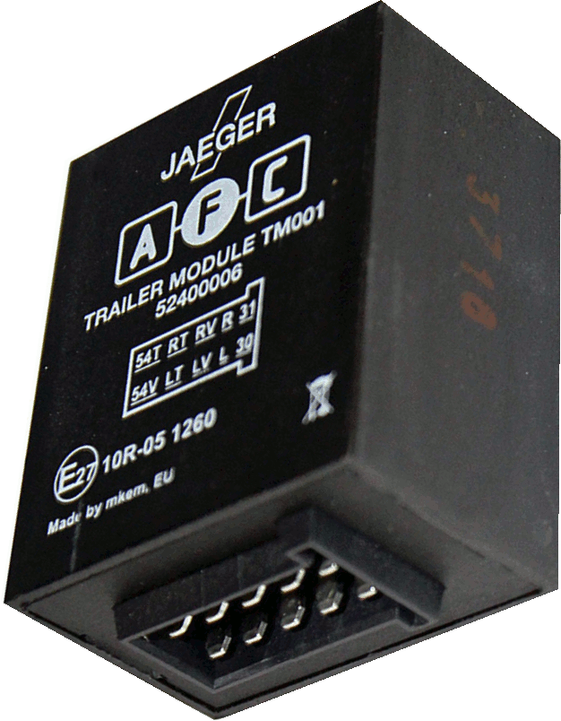
I have a Nissan Murano 2009 (made in Japan for US market). I installed a trailer towing hitch and now I want to install a towing harness. Since I live in Europe I bought Brink Wiring Kit (732614) which is specific for Nissan Murano. This kit comes with a Jaeger AFC trailer module (52400006) which basically is used for wiring the car and the trailer together to power and synchronize their lighting systems.
BACKGROUND
The AFC module (aka trailer converter) has 10-pins like in the image below. It would be helpful to note here that the converter's terminals are supposed to have the following meanings:
- 54T = the output brake signal to the Trailer
- 54V = the input brake signal from the Vehicle
- RT = the output Right turn signal to the Ttrailer
- LT = the output Left turn signal to the Ttrailer
- RV = the input Right turn signal from the Vehicle
- LV = the input Lleft turn signal from the Vehicle
- R = (*)
- L = (*)
- 31 = ground
- 30 = 12V power supply
(*) by looking at the harness' connectors and respectively at the converter's connector it looks the R and the L terminals provide somehow the same function as the RV respectively LV. However, what's important is that they are also related to the turn signals.
The tail lights look like they bypass the converter entirely, they go directly to the trailer's plug.
The towing harness kit has connectors for both the left and the right rear tail lamps. The car's rear tail lamps harness has also connectors such that the towing kit connects the car harness just by plug&play. At least for the trailer main lighting functions such as turn signals, tail lights, brake lights.
Now I think you've got the big picture of the towing kit I want to install.
PROBLEM
The problem I have with this assembly is the following. The trailer tail lights and the brake lights are working normal, but the turn signal lights are blinking at the same time when they are supposed to blink only one at a time, unless I switch on the hazard light in which case it is normal that they blink in tandem.
In order to debug this problem I tried to eliminate as many variables as possible. So I took the wiring kit at home and prepared a test bench. I connected the harness wires to the 13-pins trailer plug as per manual (see Brink Wiring Kit above, pag. 7).
In order to power the harness I used a 12V power supply so I provided +12V to the terminal #30, a ground to terminal #31. Furthermore I provide a +12V to the terminal which normally is powered from the brake relay, +12V to the terminal which normally is powered by the tail relay and finally a prepared 2 wires to selectively power the left/right turn signals.
At this point the harness is powered like when you drive the car with the headlights ON (thus tail lights are ON) while pressing the brake pedal (brake lamps are ON).
In order to test the signals that the trailer's plug receives from the harness I have built a quick testing LED panel with 2 columns of LEDs for the brake signal (red),2 for tail (green) and 2 for turn signal (yellow). Each column is powered independently (parallel circuits).
Finally I plugged my testing LED panel to the trailer plug. So the LED panels have the red brake LEDs ON and the green tail LEDs ON. Nice!
When I touch any of the turn signal terminals with a +12V wire the both turn signal lights are lighted at the same time which is exactly the same symptom I notices while I tested the harness within the physical car (see the Problem above).
To simplify the test even more I eliminated completely the harness and the LED test panel. So right now I have only the converter and my 12V power supply source.
TESTS
- I provided a +12.08V to the LV terminal and then I've checked the voltage at the other terminals:
- LT = 10.5V
- RT = 10.8V (???)
- RV = 0V
- R = 0V
- L = 12.08V
- 54T = 10.8V
- 54V = 3.5V
- The same test to the RV terminal with a 12.1V:
- RT = 10.6V
- LT = 10.8V (???)
- LV = 0V
- R = 12.1V
- L = 0V
- 54T = 10.9V
- 54V = 3.6V
- The same test to the L terminal with a 12.1V:
- RT = 10.9V
- LT = 10.6V
- RV = 0V
- LV = 12.1V
- R = 0V
- 54T = 10.9V
- 54V = 3.8V
- Finally the same test to the R terminal with a 12.1V:
- RT = 10.6V
- LT = 10.9V
- RV = 12.1V
- LV = 0V
- R = 12.1V
- 54T = 10.9V
- 54V = 3.9V
Honestly these results are confusing. Firstly I expected when apply a voltage to left to get outputs only on left. The same for right. Secondly I wouldn't expect to get a brake signal at all (see 54V/T terminals).
Given the whole specter of tests I've made what do you think would be the cause the turn signals are blinking at the same time?


