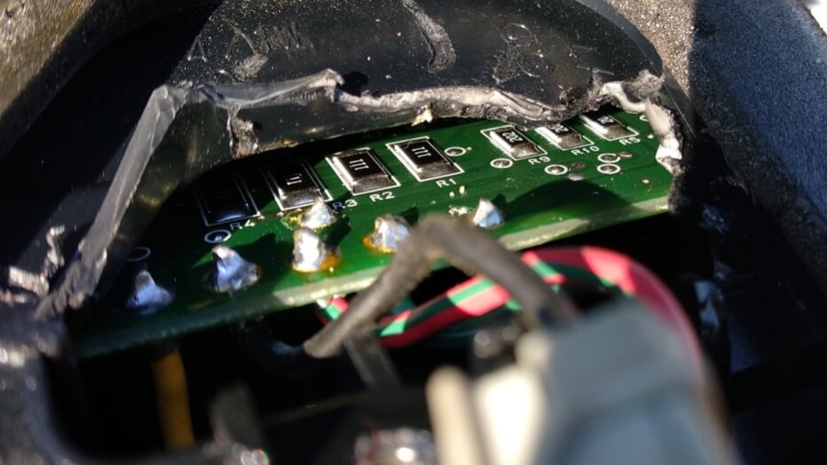
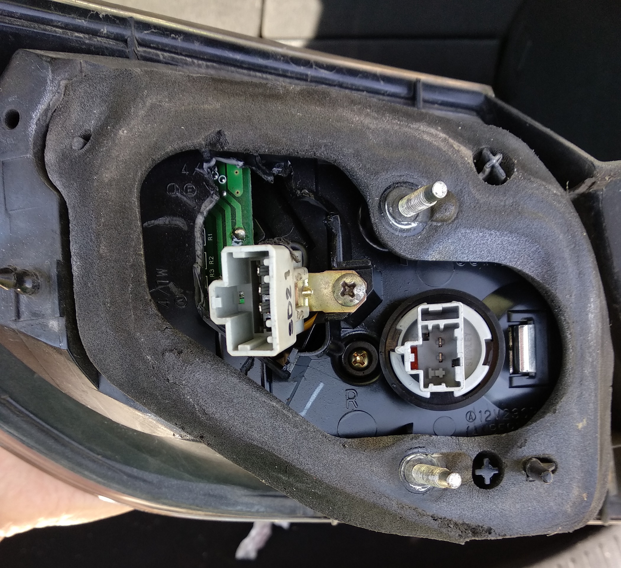
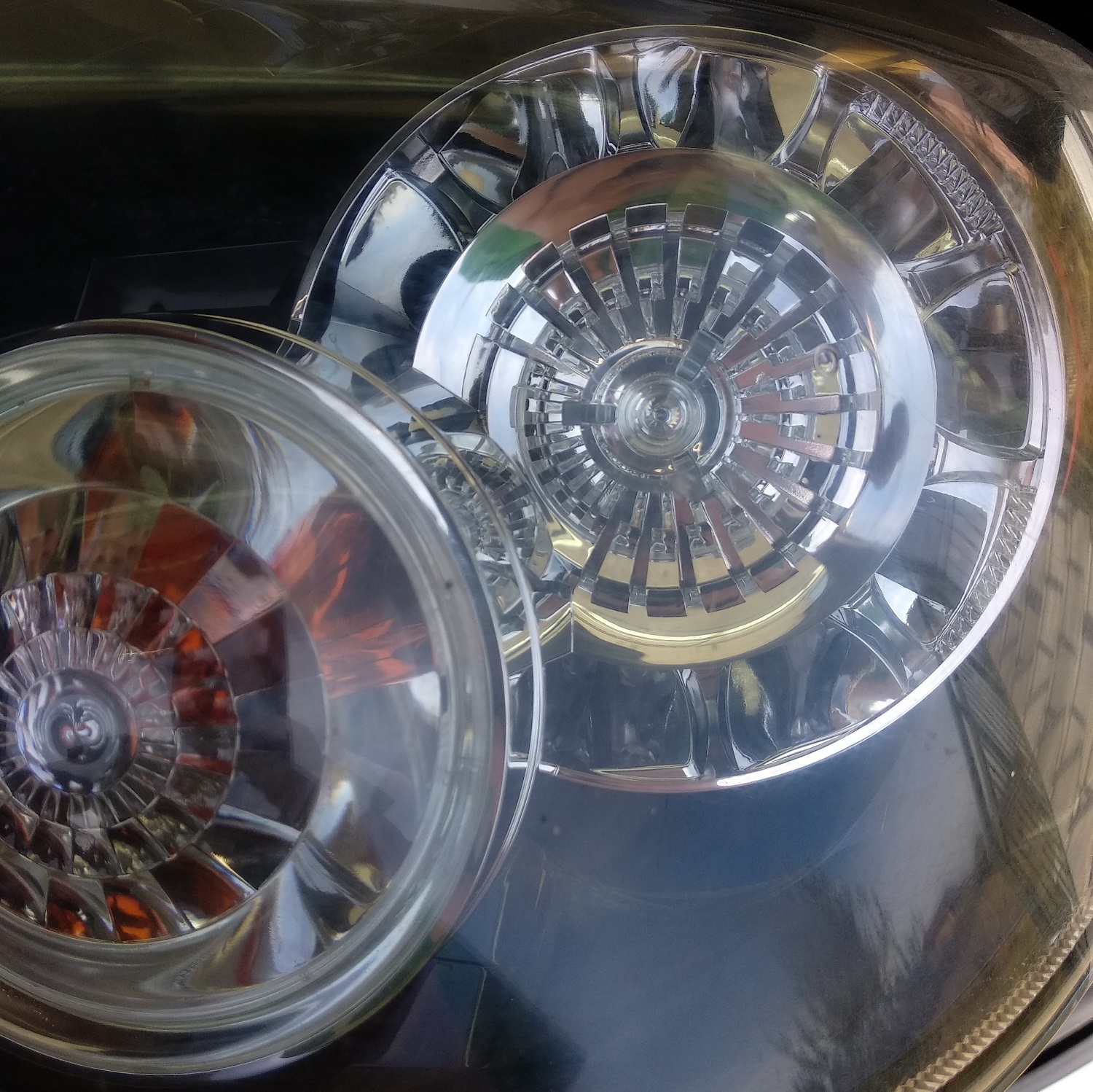
I have a problem with the rear right brake/position light on a 2005 Mazda3. Same LED lights (8 led) shine dimmer when lights are on (state 1) and goes brighter when brake are pressed (state 2). My right light has a problem it works good on state 1 but if brakes pedal is pressed it does a single flashing and than goes completely off (ignoring the state 1). If I turn off/on the lights it goes to state 1 again. I've tested the voltage of the brake pin with a test lamp and it works as it should, it's the led part that is faulty. The left LED lights works ok with both states. Temporary I have disconnected the brake pin on the right rear light so at least i can use the LEDs as position lights, but is not safe on the road and I'm worried about fail on MOT.
I've tried to remove the whole combination light and take a look at the LED circuit but it was closed from inside and can't be open via screws. I've seen that Mazda take the whole unit to do the repairs, but I want a DIY way to repair this. Has anyone worked on this lights on different car models and give me some details? Had someone try to repair this kind of lights?
If I manage to open the light via oven/cutting would I be able to repair it? If it need soldering at some loose part or changing an element (resistor/diode) I think I can do it. If someone can share a wiring diagram for this 2-state LEDs I'm curios to know.
EDIT: I've tried to swap the right faulty lights to the left part of the car and get the same faulty output. So I need some help repairing the circuit or finding a work around for this faulty LED.
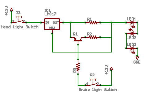
EDIT2: I've found a DIY tutorial: https://www.sau.com.au/forums/topic/371044-diy-led-tail-light-and-brake-light and a schema as seen below 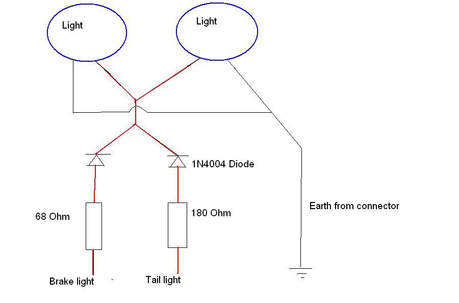 If the original manufacturer (MAZDA) has used the same schema what has possibly gone wrong in my scenario? A blown resistance or diode rectifier shouldn't make the whole circuit off in case when voltage is applied at brake wire.
Or they use a more complex circuit like this? As I saw at the circuit there were a lot of resistors looked like one resistor per LED.
Does anyone know how this resistors are connected R111= 110Ω and R202= 2kΩ and how does the circuit switch from one circuit to another
